2) Pipe slurry test: For the different concentrations of slurry, the relationship between the average flow velocity (Ï…) and the head loss (i) (indicated by the clear water column) is plotted using the same pipe diameter, and plotted as an i-Ï… curve. Then, compared with the clear water curve (i 0 -Ï… curve) of the same diameter, it can be found that when the flow rate is large to some extent, the i-Ï… line will be parallel to the i 0 -Ï… line. When less than this flow rate, the i-Ï… line will be concave from the i 0 -Ï… line. Above this flow point, the slurry exhibits a pseudo-homogeneous flow, and below the solid particles are unevenly suspended. Known as the "cutting critical flow rate" (also known as "suspension critical flow rate"). When the flow rate is slightly reduced, the bottom of the tube will show a significant load. The flow rate at this time is called "clay critical flow rate". The two critical flow rates differ by about 10%, but all of the solid particles can be removed. The critical flow rate is chosen as the parameter of the two-phase flow, which needs to be determined by technical and economic comparison according to the technical conditions of slurry transport. It is also possible to find an economic critical flow rate (Ï… e ) that meets the technical and economic conditions between or near the two critical flow rates as a design parameter. [next] 3) Extension of critical flow rate and head loss curve: Pipeline test mostly uses small pipe diameter. Therefore, it is difficult to faithfully reflect the objective conditions of large pipe diameter used in actual production, so there is a critical flow velocity of large pipe diameter and Estimation of head loss. There are usually two solutions to this: First, the extension method is to extend the curve forward. It is only applicable when the concentration and the size of the gradation are fixed. At the same time, the test pipe diameter and the actual production pipe diameter are still different. The second is the formula calculation method, that is, the calculation formula that approximates and recommends the test conditions is selected.
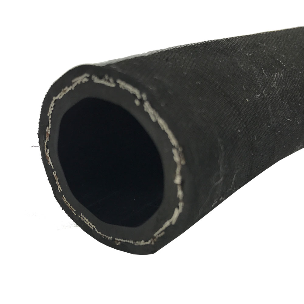
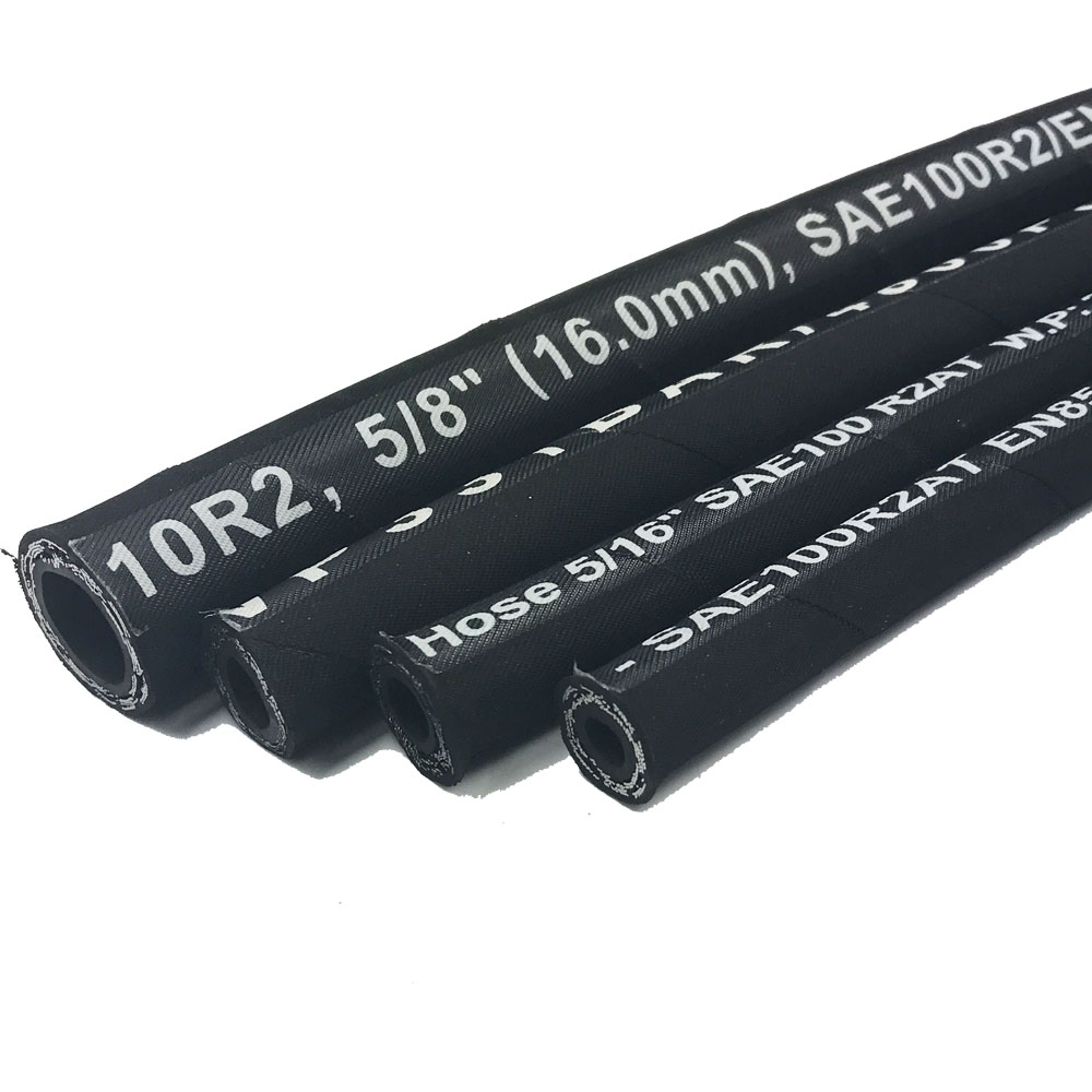
The Hydraulic Hose is recommended for hydraulic line applications. Compatible
with biodegradable hydraulic fluids like synthetic esters, polyglycols and
vegetable oils as well as petroleum-based fluids, high pressure hydraulic
systems in industry and agriculture, Mine hydraulic support, oilfield
extraction machinery, mine/ road/ construction machinery.
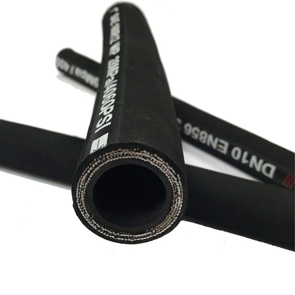
It consists of four parts, including inner layer,
middle layer, reinforcement layer and outer layer. There are main two kinds of technology
for the reinforcement, steel wire spiral or braiding, different reinforcements
ensure the various application of the hydraulic hose.
Hydraulic Hose Hydraulic Rubber Hose,Hydraulic Pipe,Hydraulic Tubing,Hydraulic High Pressure Hose Hebei Orient Rubber & Plastic Co., Ltd. , https://www.hiteckhose.com
1) Pipeline water test: This test is mainly to test whether the measurement system works normally, and propose the pipeline water resistance and the calculation of the pipe wall roughness. In order to determine the change in the roughness of the pipe wall after transporting the slurry, a water test is usually carried out before and after the pipe slurry transport test for comparison. The relationship between the average flow velocity (Ï…) and the head loss (i 0 ) of different pipe diameters obtained from the water test is plotted as a graph (Fig. 4). 
After obtaining the critical flow rate (Ï… e ) of various concentrations, the head loss value (i e ) at each critical flow rate is obtained. D (pipe diameter) - P (concentration) - Ï… e (critical flow rate) can be plotted. A graph of the relationship between the relationship graph and DPi e (critical head loss) (Fig. 5, Fig. 6). A peak and a valley will appear on each of the two graphs. In the curve valley section, the head loss is small and the energy consumption is also reduced, which is an ideal range for conveying slurry. For example, the weight concentration in Figures 5 and 6 is 38 to 48%, which is the ideal concentration section for conveying the slurry, of which 45% is most desirable. 
 [next]
The parameters generally to be determined by the extension method are critical flow rate and head loss. The main purpose of extending the critical flow rate is to infer the change in the critical flow rate outside the range of the test tube (increase or decrease). When performing the curve extension, it is necessary to fully estimate the possible effects on the physical properties, particle size composition and flow state of the slurry due to the change of the pipe diameter, and these effects will bring certain errors to the extended critical flow rate curve.
The head loss extension at the critical flow rate first assumes that the head loss (i e ) of the slurry is the sum of the head loss of the clean water (i 0 ) and the additional head loss (Δ i ) increased by mixing the fresh water, ie:
Δi=i e -i 0
A set of Δi values ​​can be obtained by testing different concentrations of slurry in pipes of different diameters. At this point, the curve can be extended. However, the application of this extension curve should be sufficient to estimate the error in the original test; at the same time, the problem of grain refinement that may be brought about in long-term transportation should be considered. Therefore, when using such a curve, it is generally multiplied by a safety factor of 1.1 to 1.2.
Regardless of the extension data obtained by the extension method or the calculation formula method, as long as the applicable pipe diameter is not very different from the pipe diameter used in the original test, relatively speaking, it has a certain reliability. If the difference between the two diameters is too great, whether the critical flow rate and head loss derived from the extension can be used as the design basis remains to be verified.
C Slurry Settlement Test The main purpose of the slurry settling test is to detect the sudden deposition of solid augmentation of the pipeline, which may cause difficulty in restarting. The specific test content is as follows:
a Physical and chemical properties of the slurry (1) Inspection of the nature of the material: When the pipeline stops production, whether there will be recrystallization or gelation between the particles.
(2) Granular composition test: Whether it is possible to change the particle size composition in long-distance pipeline transportation.
(3) Solids down test: Look for the “critical inclination†of the solid material in the slurry that may fall, to determine the maximum allowable slope that can be used for pipe laying.
(4) Test of slurry flow performance when restarting transportation: It is tested whether the flow state of the slurry and other flow properties and the original slurry change when the pipeline is restarted.
b Slurry static test The slurry is poured into the riser and allowed to stand for 15 to 30 days. Observe the change of the solid particle distribution in the slurry to check whether the distribution of solid particles in the high concentration slurry is stable or nearly stable.
In addition to the above-mentioned test items, foreign countries generally require abrasion tests of equipment and pipelines. Some mines in China also have this requirement in recent years. In addition, the material powder (refined) test is an important test content, but the metal slurry, it is generally not required. 


Slurry tube and trough conveying test (2)
(2) Pipeline critical flow rate and head loss test: