Standards :ANSI B16.5, ANSI B16.47 Series A & B, MSS SP44, ASA, API-605, AWWA, Custom Drawings
Size : 1/2″ (15 NB) to 48″ (1200NB)
Class : 150 LBS, 300 LBS, 600 LBS, 900 LBS, 1500 LBS, 2500 LBS, DIN Standard ND-6,10, 16, 25, 40 Etc.
Flange Face Type : Flate Face (FF), Raised Face (RF), Ring Type Joint (RTJ)
DIN : DIN2527, DIN2566, DIN2573, DIN2576, DIN2641, DIN2642, DIN2655, DIN2656, DIN2627, DIN2628, DIN2629, DIN 2631, DIN2632, DIN2633, DIN2634, DIN2635, DIN2636, DIN2637, DIN2638, DIN2673
BS : BS4504 , BS4504, BS1560, BS10
Stainless Steel Slip On Flanges : ASTM A 182, A 240 F 304, 304L, 304H, 316, 316L, 316Ti, 310, 310S, 321, 321H, 317, 347, 347H,904L
Alloy Steel Slip On Flanges : ASTM / ASME A/SA 182 & A 387 F1, F5, F9, F11, F12, F22, F91
Duplex & Super Duplex Steel Slip On Flanges : ASTM / ASME A/SA 182 F 44, F 45, F51, F 53, F 55, F 60, F 61
Carbon Steel Slip On Flanges :ASTM / ASME A/SA 105 ASTM / ASME A 350 , ASTM A 181 LF 2 / A516 Gr.70 A36, A694 F42, F46, F52, F60, F65, F70
Copper Alloy Steel Slip On Flanges : ASTM SB 61 , SB62 , SB151 , SB152 UNS No. C 70600 (Cu-Ni 90/10), C 71500 (Cu-Ni 70/30), UNS No. C 10100, 10200, 10300, 10800, 12000, 12200,
Nickel Alloy Slip On Flanges : ASTM SB564, SB160, SB472, SB162 Nickel 200 (UNS No. N02200), Nickel 201 (UNS No. N02201), Monel 400 (UNS No. N04400), Monel 500 (UNS No. N05500), Inconel 800 (UNS No. N08800), Inconel 825 (UNS No. N08825), Inconel 600 (UNS No. N06600), Inconel 625 (UNS No. N06625), Inconel 601 (UNS No. N06601), Hastelloy C 276 (UNS No. N10276), Alloy 20 (UNS No. N08020).
Slip On Flange,Slip On Pipe Flange,Butt Weld Flange,Spectacle Blind Flange Hebei Mingda International Trading Co.,Ltd , http://www.mingdacasting.com
Second, functional design requirements (range range):
DC voltage - 200mV2V20V200V1000V
AC voltage - 200mV2V20V200V700V
DC Current (DCA) - 2mA20mA200mA20A
AC Current (ACA) - 2mA20mA200mA
Resistance (OHM) --―2002K20K200K2M20M
Third, the main chip: MSP430FE42X
Fourth, the operating mode: Buttons - DCV button, ACV button, DCA button, ACA button, OHM button five, block diagram:
When performing AD measurements, the MSP430FE42X can select either an external reference source or an internal reference source.
Here when measuring the voltage and current, select the internal reference source 1.25V, so when the external voltage to be measured is 0.625V, the AD sampled value is 65535, when the measured voltage is -0.625, the AD sampled value is 0. Since the design's minimum range is 0.2V, it needs to be scaled up to 0.625V to make it full-scale, and then converted according to the displayed number of bits, that is, 0-20000 corresponds to 0-32767. The actual minimum resolution is 0.2/32767V = 6 microvolts.
When the voltage to be measured is greater than 0.2V, a partial pressure treatment must be performed. Generally, a voltage divider of 10 times is used, for example, 0.2V at 2V. The voltage divider is shown in Figure 1. 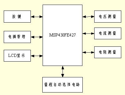

Figure 1 Voltage divider 
Figure 2 Current divider
The above is the case of measuring DC voltage or DC current. When measuring AC voltage or AC current, it must be rectified. The rectifier circuit is shown in Figure 3. 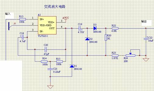
Figure 3 AC rectifier circuit
The measurement of resistance is different from the measurement of voltage and current. The schematic diagram is shown in Figure 4. 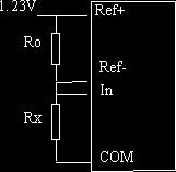
Six, a brief analysis of the actual implementation of the circuit:
1, DC voltage measurement:
The voltage to be measured passes through a voltage divider to generate different voltage values ​​across the voltage divider resistors. At this time, the voltage of the input MCU is determined according to the voltage to be measured. Here, the HC4051 is used to select the voltage to be measured. Since the voltage to be measured may be as high as 1000V, Panasonic's PHOTORELAY (its input is up to 1000V) is selected as the input of the voltage divider. When the appropriate voltage divider is selected, the voltage is about 3 times of the amplifier circuit composed of TLV2211 (AD sampling full scale), and then the range conversion (0-20000 corresponds to 0-32767) can be obtained. Measure voltage value.
2, AC voltage measurement:
The AC voltage measurement shares a voltage divider with the DC voltage measurement. After being divided, the voltage to be measured is rectified by the AC rectifying circuit composed of the TLV2211 and then enters the amplifying circuit for measurement.
3, DC current measurement:
Because the current to be measured is up to 200mA, the current through the analog switch can be small. Therefore, AQV201 (500mA load current at 40V) is used as the current selection. The measured current is divided into the amplifier circuit before being sent to the AD.
4, AC current measurement:
The AC current measurement shares a voltage divider with the DC current measurement. The difference is that after the voltage is divided, it will enter the AC rectification circuit, and then it will enter the amplifier circuit and be sent to the AD.
5, resistance measurement:
The resistance measurement circuit selects the MAX4638 analog switch with a small internal resistance to access the reference resistors of different ranges to measure the resistance of the resistance to be measured. The AD uses an external reference voltage. The reference voltage is sent to the reference terminal through the subtraction circuit to obtain the voltage on the reference resistor, and the voltage on the resistance to be measured is directly sent to the measurement terminal.
6, finally:
Since the input impedance of the MSP430FE42X is 500k, a follower is added to the AD input to increase its input impedance.
Slip On Flanges Specification :
Slip On Flanges Material & Grades :

Automatic range multimeter design plan [Figure]
First, the design goal: 4 1/2 million meters (19999), the minimum resolution of 6 microvolts, automatically select the range. In the same way, when measuring the current, it is also processed so that the current becomes a voltage before it can be measured. The current measurement principle is shown in Figure 2. Please note that the right 20A input in Figure 2 is directly connected, of course, you can also add a 20A fuse. The AC/DC conversion circuit consists of an in-phase amplifier A1, rectifiers D2 and D3, blocking capacitors C18 and C19, smoothing filters R22 and C22, and R24 is a calibration resistor. This circuit can get the effective value of the input sine wave. D1 is used to reduce nonlinear distortion. Resistance measurement uses a proportional method, that is, when the current flowing through the resistance to be measured and the reference resistor are the same, Uin/Uref=Rx/Rref, according to the AD conversion characteristics of the FE42X, when the input voltage is half full of the reference voltage, That is when the resistance to be measured is half of the reference resistance. Therefore, the reference resistance of 200 ohms is 400 ohms. Assuming that the resistance to be measured is 100 ohms, since the voltage across the reference resistance and the resistance to be measured is 1.23 V at this time, the reference voltage is 1.23*(400/500)V, and the input The voltage is 1.23*(100/500), and when the input voltage is 1.23*2/5 full scale, the current AD value is half-100 ohms of full scale. Of course, the AD at this time is the conversion of the range 0-20000 corresponding to 0-32767.